Electro-Mechanical Actuators & Their Drives
Contents
Stepper Motors
Variable Reluctance Motors
Hybrid Motors
INTRODUCTION
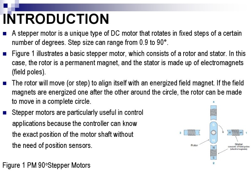
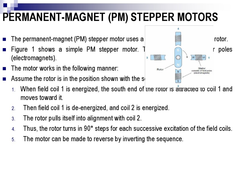
Figure 1 PM 90oStepper Motors
A stepper motor is a unique type of DC motor that rotates in fixed steps of a certain number of degrees. Step size can range from 0.9 to 90°.
Figure 1 illustrates a basic stepper motor, which consists of a rotor and stator. In this case, the rotor is a permanent magnet, and the stator is made up of electromagnets (field poles).
The rotor will move (or step) to align itself with an energized field magnet. If the field magnets are energized one after the other around the circle, the rotor can be made to move in a complete circle.
Stepper motors are particularly useful in control
applications because the controller can know
the exact position of the motor shaft without
the need of position sensors.
Introduction
Thisisdonebysimplycountingthenumberofstepstakenfromaknownreferenceposition.
Stepsizeisdeterminedbythenumberofrotorandstatorpoles,andthereisnocumulativeerror(theangleerrordoesnotincrease,regardlessofthenumberofstepstaken).
Infact,moststeppermotorsystemsoperateinopen-loopcontrolmodeinwhich,thecontrollersendsthemotoradeterminednumberofstepcommandsandassumesthemotorgoestotherightplace.
Acommonexampleisthepositioningoftheread/writeheadinafloppydiskdrive.
Steppershaveinherentlylowvelocityandthereforearefrequentlyusedwithoutgearreductions
Steppermotorscaneasilybecontrolledtoturnat1rpmorlesswithcompleteaccuracy.
Therearethreetypesofsteppermotors:
permanentmagnet,variablereluctance,andhybrid.
PERMANENT-MAGNET (PM) STEPPER MOTORS
Thepermanent-magnet(PM)steppermotorusesapermanentmagnetfortherotor.
Figure1showsasimplePMsteppermotor.Thefieldconsistsoffourpoles(electromagnets).
Themotorworksinthefollowingmanner:
Assumetherotorisinthepositionshownwiththesouthendup:
1.Whenfieldcoil1isenergized,thesouthendoftherotorisattractedtocoil1andmovestowardit.
2.Thenfieldcoil1isde-energized,andcoil2isenergized.
3.Therotorpullsitselfintoalignmentwithcoil2.
4.Thus,therotorturnsin90°stepsforeachsuccessiveexcitationofthefieldcoils.
5.Themotorcanbemadetoreversebyinvertingthesequence.
PM Stepper Motors, Cont.
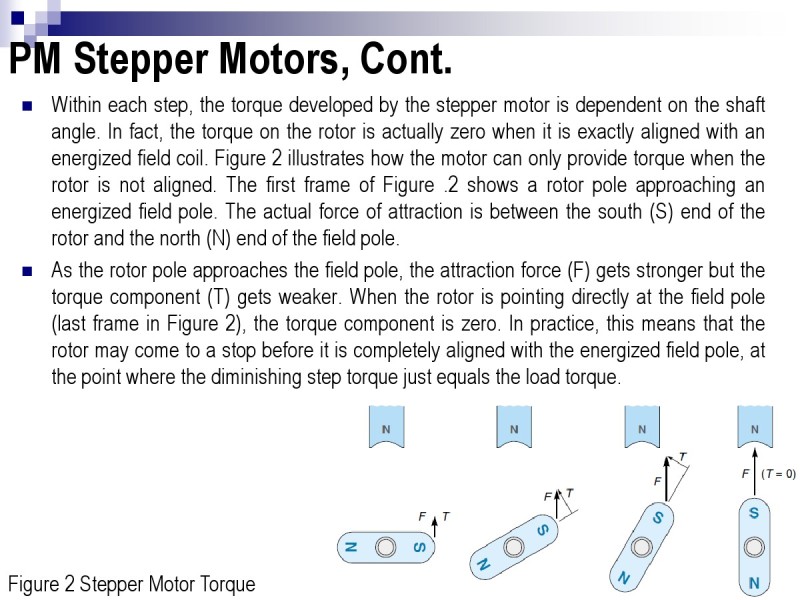
Withineachstep,thetorquedevelopedbythesteppermotorisdependentontheshaftangle.Infact,thetorqueontherotorisactuallyzerowhenitisexactlyalignedwithanenergizedfieldcoil.Figure2illustrateshowthemotorcanonlyprovidetorquewhentherotorisnotaligned.ThefirstframeofFigure.2showsarotorpoleapproachinganenergizedfieldpole.Theactualforceofattractionisbetweenthesouth(S)endoftherotorandthenorth(N)endofthefieldpole.
Astherotorpoleapproachesthefieldpole,theattractionforce(F)getsstrongerbutthetorquecomponent(T)getsweaker.Whentherotorispointingdirectlyatthefieldpole(lastframeinFigure2),thetorquecomponentiszero.Inpractice,thismeansthattherotormaycometoastopbeforeitiscompletelyalignedwiththeenergizedfieldpole,atthepointwherethediminishingsteptorquejustequalstheloadtorque.
Figure2StepperMotorTorque
Modes of Operation
The stepper motor has two modes of operation: single step and slew.
In the single-step mode or bidirectional mode, the frequency of the steps is slow enough to allow the rotor to (almost) come to a stop between steps.
Figure 3 shows a graph of position versus time for single-step operation. For each step, the motor advances a certain angle and then stops.
If the motor is only lightly loaded, overshoot and oscillations may occur at the end of each step as shown in figure 3.
Figure3PositionVstime
Single Step Operation Mode
Thebigadvantageofsingle-stepoperationisthat,
1.eachstepiscompletelyindependentfromeveryotherstep—thatis,themotorcancometoadeadstoporevenreversedirectionatanytime.
2.therefore,thecontrollerhascompleteandinstantaneouscontrolofthemotor’soperation.
3.thereisahighcertaintythatthecontrollerwillnotlosecount(andhencemotorposition)becauseeachstepissowelldefined.
The disadvantage of single-step modeis that,
1.the motion is slow . A typical single-step rate is 5 steps/second which translates to 12.5 rpm for a 15°/step motor.
Slew Mode
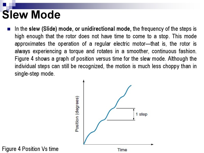
Intheslew(Slide)mode,orunidirectionalmode,thefrequencyofthestepsishighenoughthattherotordoesnothavetimetocometoastop.Thismodeapproximatestheoperationofaregularelectricmotor—thatis,therotorisalwaysexperiencingatorqueandrotatesinasmoother,continuousfashion.Figure4showsagraphofpositionversustimefortheslewmode.Althoughtheindividualstepscanstillberecognized,themotionismuchlesschoppythaninsingle-stepmode.
Figure4PositionVstime
Slew Mode,Cont.
Asteppermotorintheslewmodecannotstoporreversedirectioninstantaneously.
Ifattempted,therotationalinertiaofthemotorwouldmostlikelycarrytherotoraheadafewstepsbeforeitcametorest.
Thestep-countintegritywouldbelost.
Itispossibletomaintainthestepcountintheslewmodebyslowlyrampingupthevelocityfromthesingle-stepmodeandthenrampingdownattheendoftheslew.
Thismeansthecontrollermustknowaheadoftimehowfarthemotormustgo.
Typically,theslewmodeisusedtogetthemotorpositioninthe“imprecise,”andthenthefineadjustmentscanbemadewithsinglesteps.
Slewingmovesthemotorfasterbutincreasesthechancesoflosingthestepcount.
Current Control (Mode) Amplifier Cont.
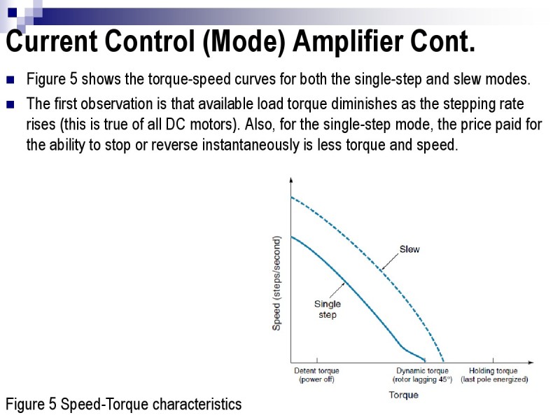
Figure 5 shows the torque-speed curves for both the single-step and slew modes.
The first observation is that available load torque diminishes as the stepping rate rises (this is true of all DC motors). Also, for the single-step mode, the price paid for the ability to stop or reverse instantaneously is less torque and speed.
Figure5Speed-Torquecharacteristics
Speed-Torque Characteristics
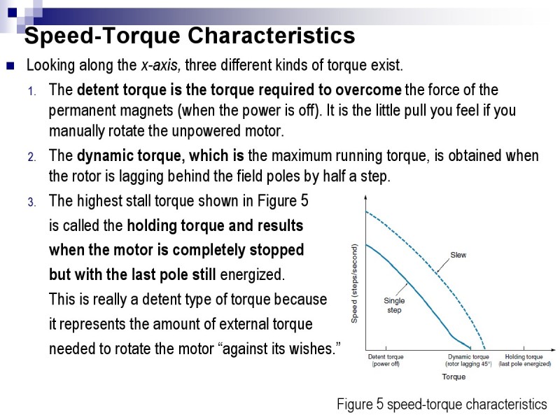
Looking along the x-axis, three different kinds of torque exist.
1.The detent torque is the torque required to overcome the force of the permanent magnets (when the power is off). It is the little pull you feel if you manually rotate the unpowered motor.
2.The dynamic torque, which is the maximum running torque, is obtained when the rotor is lagging behind the field poles by half a step.
3.The highest stall torque shown in Figure 5
is called the holding torque and results
when the motor is completely stopped
but with the last pole still energized.
This is really a detent type of torque because
it represents the amount of external torque
needed to rotate the motor “against its wishes.”
Figure5speed-torquecharacteristics
Excitation Modes for PM Stepper Motors
Stepper motors come with a variety of winding and rotor combinations.
In addition, there are different ways to sequence energy to the field coils.
All these factors determine the size of each step. Phase refers to the number of separate winding circuits.
There are two-, three-, and four-phase steppers, which are discussed next.
Two-Phase (Bipolar) Stepper Motors
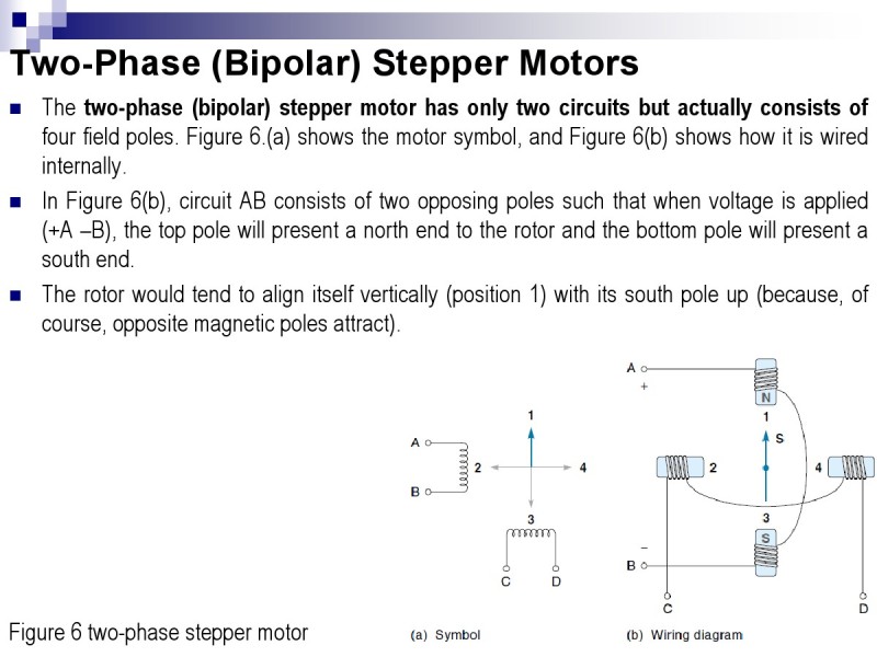
The two-phase (bipolar) stepper motor has only two circuits but actually consists of
four field poles. Figure 6.(a) shows the motor symbol, and Figure 6(b) shows how it is wired
internally.
In Figure 6(b), circuit AB consists of two opposing poles such that when voltage is applied
(+A –B), the top pole will present a north end to the rotor and the bottom pole will present a
south end.
The rotor would tend to align itself vertically (position 1) with its south pole up (because, of
course, opposite magnetic poles attract).
Figure 6 two-phase stepper motor
Clock wise (CW) & Counter CW (CCW) motion
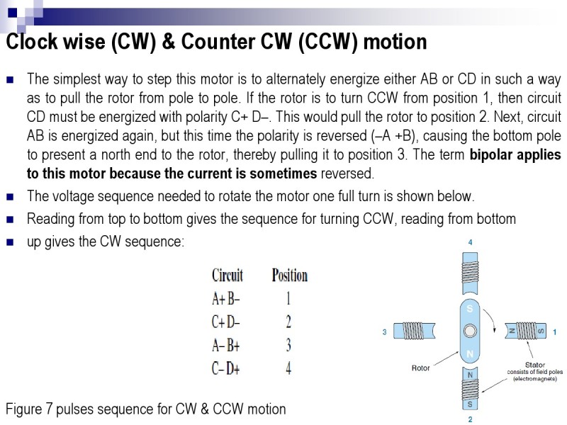
The simplest way to step this motor is to alternately energize either AB or CD in such a way
as to pull the rotor from pole to pole. If the rotor is to turn CCW from position 1, then circuit
CD must be energized with polarity C+ D–. This would pull the rotor to position 2. Next, circuit
AB is energized again, but this time the polarity is reversed (–A +B), causing the bottom pole
to present a north end to the rotor, thereby pulling it to position 3. The term bipolar applies
to this motor because the current is sometimes reversed.
The voltage sequence needed to rotate the motor one full turn is shown below.
Reading from top to bottom gives the sequence for turning CCW, reading from bottom
up gives the CW sequence:
Figure 7 pulses sequence for CW & CCW motion
Dual Excitation Mode
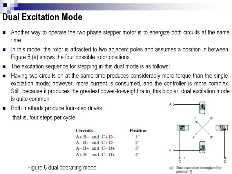
Another way to operate the two-phase stepper motor is to energize both circuits at the same
time.
In this mode, the rotor is attracted to two adjacent poles and assumes a position in between.
Figure 8.(a) shows the four possible rotor positions.
The excitation sequence for stepping in this dual mode is as follows:
Having two circuits on at the same time produces considerably more torque than the singleexcitation
mode; however, more current is consumed, and the controller is more complex.
Still, because it produces the greatest power-to-weight ratio, this bipolar, dual excitation mode
is quite common.
Both methods produce four-step drives,
that is, four steps per cycle
Figure 8 dual operating mode
Half Step Mode
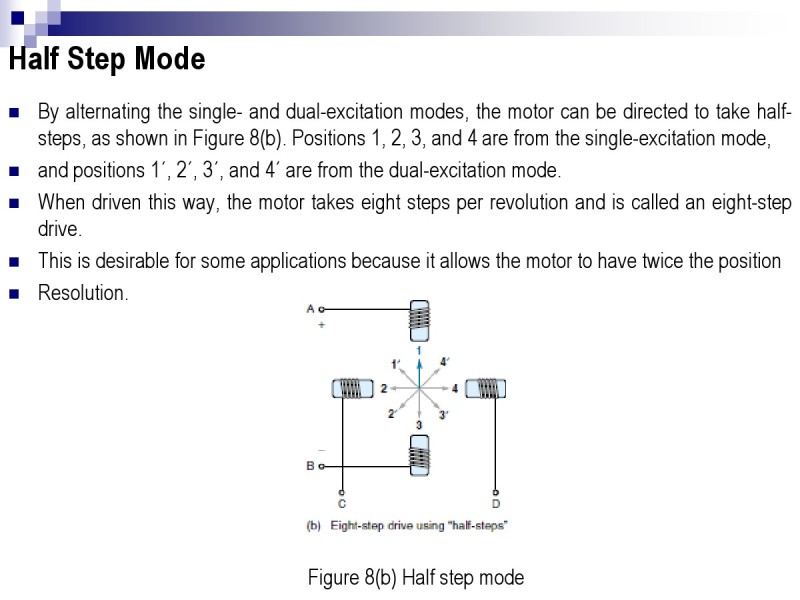
Byalternatingthesingle-anddual-excitationmodes,themotorcanbedirectedtotakehalf-steps,asshowninFigure8(b).Positions1,2,3,and4arefromthesingle-excitationmode,
andpositions1´,2´,3´,and4´arefromthedual-excitationmode.
Whendriventhisway,themotortakeseightstepsperrevolutionandiscalledaneight-stepdrive.
Thisisdesirableforsomeapplicationsbecauseitallowsthemotortohavetwicetheposition
Resolution.
Figure8(b)Halfstepmode
Variable-Reluctance Stepper Motors
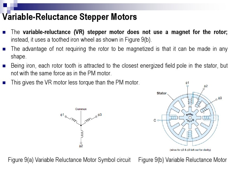
The variable-reluctance (VR) stepper motor does not use a magnet for the rotor;
instead, it uses a toothed iron wheel as shown in Figure 9(b).
The advantage of not requiring the rotor to be magnetized is that it can be made in any
shape.
Being iron, each rotor tooth is attracted to the closest energized field pole in the stator, but
not with the same force as in the PM motor.
This gives the VR motor less torque than the PM motor.
Figure 9(a) Variable Reluctance Motor Symbol circuit Figure 9(b) Variable Reluctance Motor
Variable-Reluctance Stepper Motors
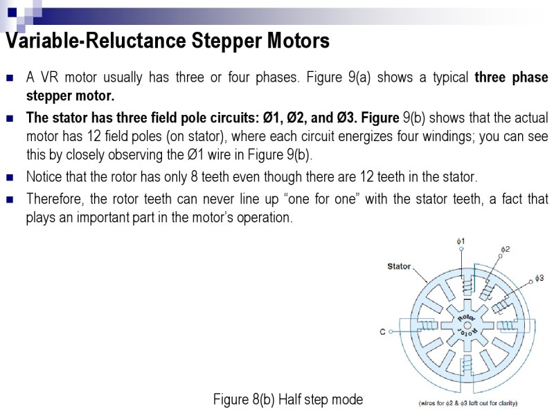
AVRmotorusuallyhasthreeorfourphases.Figure9(a)showsatypicalthreephasesteppermotor.
Thestatorhasthreefieldpolecircuits:Ø1,Ø2,andØ3.Figure9(b)showsthattheactualmotorhas12fieldpoles(onstator),whereeachcircuitenergizesfourwindings;youcanseethisbycloselyobservingtheØ1wireinFigure9(b).
Noticethattherotorhasonly8teetheventhoughthereare12teethinthestator.
Therefore,therotorteethcanneverlineup“oneforone”withthestatorteeth,afactthatplaysanimportantpartinthemotor’soperation.
Figure8(b)Halfstepmode
VR Motor principle of Operation
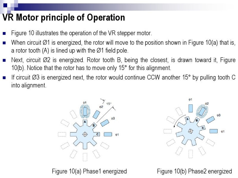
Figure 10 illustrates the operation of the VR stepper motor.
When circuit Ø1 is energized, the rotor will move to the position shown in Figure 10(a) that is,
a rotor tooth (A) is lined up with the Ø1 field pole.
Next, circuit Ø2 is energized. Rotor tooth B, being the closest, is drawn toward it, Figure
10(b). Notice that the rotor has to move only 15° for this alignment.
If circuit Ø3 is energized next, the rotor would continue CCW another 15° by pulling tooth C
into alignment.
Figure 10(a) Phase1 energized Figure 10(b) Phase2 energized
VR Motor principle of Operation
ThestepangleoftheVRmotoristhedifferencebetweentherotorandstatorangles.ForthemotorofFigure10,theanglebetweenthefieldpolesis30°,andtheanglebetweentherotorpolesis45°.Therefore,thestepis15°(45°–30°=15°).
Byusingthisdesign,theVRsteppermotorcanachieveverysmallsteps(lessthan1°).
Smallstepsizeisoftenconsideredtobeanadvantagebecauseitallowsformoreprecisepositioning
TheVRsteppermotorhasanumberoffunctionaldifferenceswhencomparedwiththePMtype.Becausetherotorisnotmagnetized,itisweaker(lesstorque)thanasimilar-sizedPMsteppermotor.Also,ithasnodetenttorquewhenthepowerisoff,whichcanbeanadvantageordisadvantagedependingontheapplication.
Finally,becauseofthesmallstepsizeandreduceddetenttorque,theVRsteppermotorhasmoreofatendencytoovershootandskipastep.Thisisaseriousmatterifthemotorisbeingoperatedopen-loop,wherepositionismaintainedbykeepingtrackofthenumberofstepstaken.
Tosolvetheproblem,somesortofdampingmayberequired.Thiscanbedonemechanicallybyaddingfrictionorelectricallybyprovidingaslightbrakingtorquewithadjacentfieldpoles.
Hybrid Stepper Motors
The hybrid stepper motor combines the features of the PM and VR stepper motors
The rotor is toothed, which allows for very small step angles (typically 1.8°), and it has a permanent magnet providing a small detent torque even when the power is off.
Recall that the step size of a PM motor is limited by the difficulty in making a multipole magnetized rotor.
There is simply a limit to the number of different magnetizations that can be imposed on a single iron rotor.
The VR stepper motor gets around this by substituting iron teeth (of which there can be many) for magnetized poles on the rotor.
This approach allows for a small step angle, but it sacrifices the strength and detent torque qualities of the PM motor.
The hybrid motor can effectively magnetize a multi-toothed rotor and thus has the desirable properties of both the PM and VR motors.
Hybrid Stepper Motors
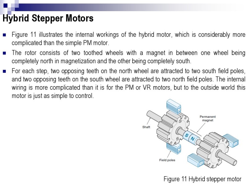
Figure 11 illustrates the internal workings of the hybrid motor, which is considerably more
complicated than the simple PM motor.
The rotor consists of two toothed wheels with a magnet in between one wheel being
completely north in magnetization and the other being completely south.
For each step, two opposing teeth on the north wheel are attracted to two south field poles,
and two opposing teeth on the south wheel are attracted to two north field poles. The internal
wiring is more complicated than it is for the PM or VR motors, but to the outside world this
motor is just as simple to control.
Figure 11 Hybrid stepper motor
Hybrid Stepper Motors
The theory of operation of the hybrid motor is similar to the VR motor in that the rotor and
stator have a different number of teeth, and for each step, the closest energized teeth are
pulled into alignment. However, the principles of magnetic require that, at any one time, half
the poles be north and the other half be south.
Figure 11 Hybrid stepper motor
- 11- Electro-Mechanical Actuators & Their Drives 2
- Actuators
- Clock wise (CW) & Counter CW (CCW) motion
- Cont.
- Current Control (Mode) Amplifier Cont.
- Dual Excitation Mode
- Excitation Modes for PM Stepper Motors
- Half Step Mode
- Hybrid Motors
- Hybrid Stepper Motors
- Introduction
- Modes of Operation
- PERMANENT-MAGNET (PM) STEPPER MOTORS
- PM Stepper Motors
- Sensors & Actuators
- Single Step Operation Mode
- Slew Mode
- Speed-Torque Characteristics
- Stepper Motors
- Two-Phase (Bipolar) Stepper Motors
- Variable Reluctance Motors
- Variable-Reluctance Stepper Motors
- VR Motor principle of Operation

